
Making a Robot, part 2
in which our intrepid adventurer rolls up his sleeves and engages with Chinese hardware and software

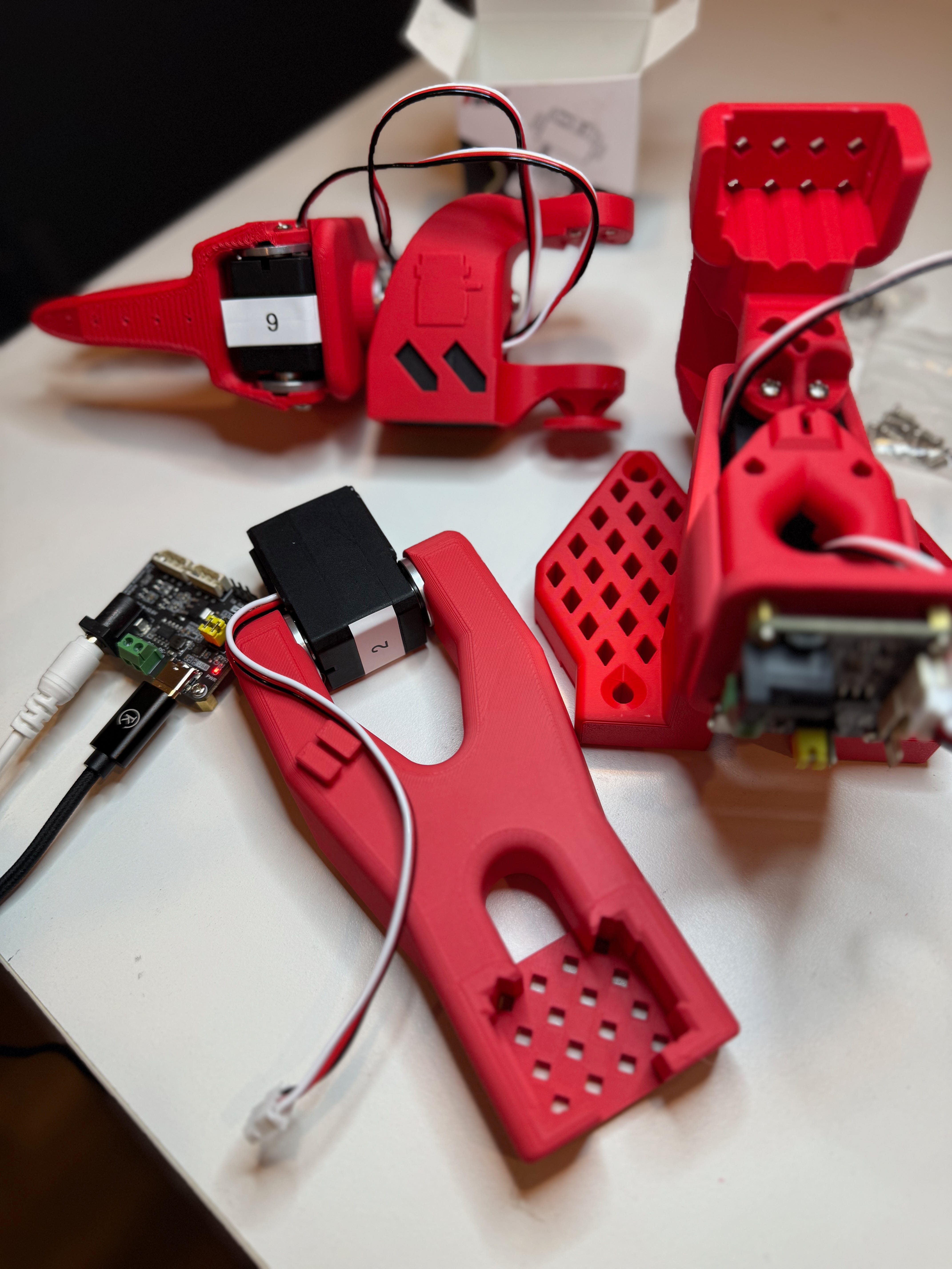
Having completed the printing of the arms and acquired the components, our next step is to program the servos and assemble the devices. The Leader and Follower arms in the SO-100 design are nearly identical, but not exactly, as you’ll see as we progress. At a high level, we’re going to connect each servo to the desktop Win11 box, assign them each a number (1 through 6), take out the gears in the Leader servos, and assemble into a finished arm.
The cleanest way to do this part of the project is to download the Le Robot python package which has a command line way to get info from the servos and reprogram. But I already had the manufacturer’s software downloaded from this link and watched a YouTube video by The Robot Studio explaining step by step how to reset the servo IDs, so I just did it that way instead.
Plugging in the USB cable makes the power LED on the control board light up, but the servo won’t show up even if it’s connected. That needs power to the board and fortunately I got the right power supply because it says 9-12v on the board and I have a 12v power supply. I thought that might have been too much for the servos, which per the manufacturer top out at 7.4v, but it could just mean that’s all they can take before they stall, not their max capacity. And maybe the controller steps that down anyway? Not sure.
The software is super basic, but gets the job done. You’ll have to make sure the COM port is correct; one of my boards was COM3 and the other COM4, not sure why that happened since I used the same USB C cable to connect to both, and not simultaneously.
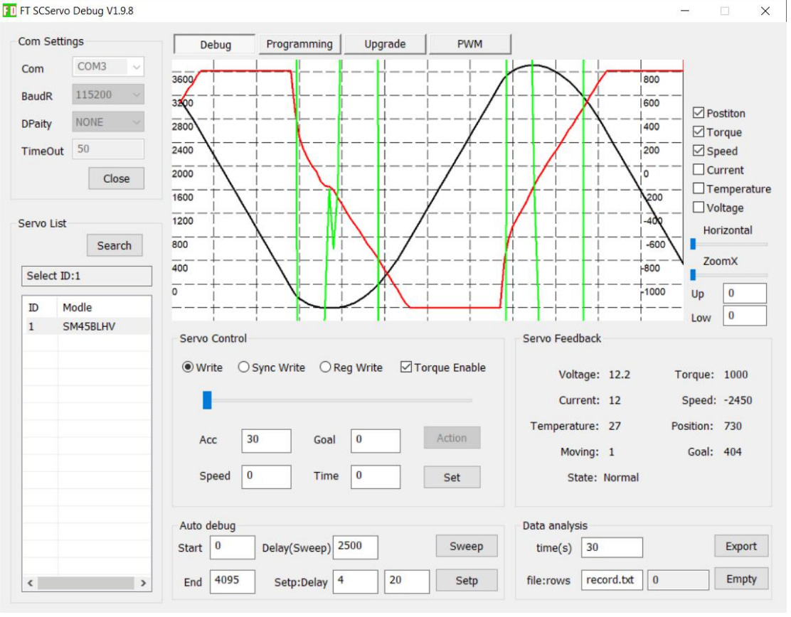
Next, you’ll change the BaudR (baud rate, of course) to 1000000, the highest setting. Have no idea why that is and why that’s not the default and why that default doesn’t persist after you close the software program and reopen it. But it does. So check that before moving on.
Then click “open” to make sure you’re sending data over that port, then click “search.” You should get an ID of 1 and the “Modle” of STS3215. If you see lines moving on the graph, you’re good. If not, click the model name or ID and it should fire up. The green line is speed and the black line is position.
The positions go from 0 to 4095 and as far as I know can’t be changed. If you’re smart enough to do this before assembling your robot arm (ahem) then you can set them all to 2048 and put the metal collar on, the one with the splines to match the splines of the drive shaft, and then lock it down. Like the man in the video instructs. Or you could be an excited dumbass who thinks he knows better.
Next step is to assign an ID. This is also simple, but a bit clunky. Click over to the “programming” tab (just above the graph with the lines) and you’ll see a whole list of things that you can fiddle with and where they’re saved and whether you can only read or read and write.
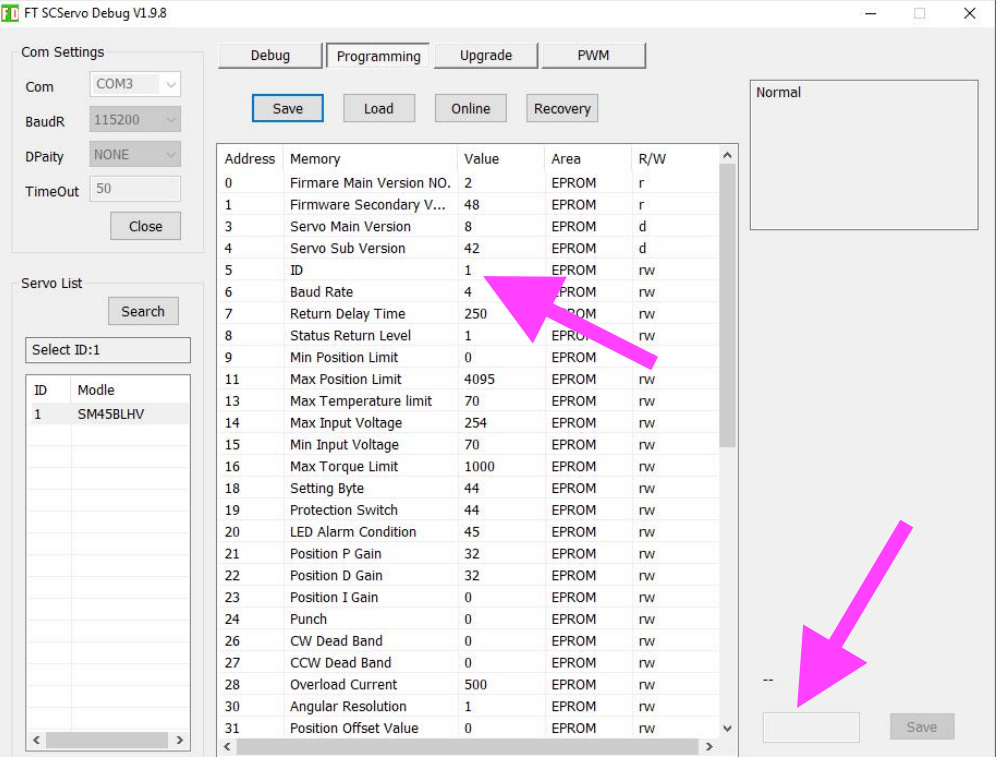
The first entry that you can "rw" is address 5 for the ID. Click that. It’ll highlight in blue. Down in the lower right corner, next to the “save” button, is a window where you can reset the ID number of the servo. Type in the number and hit save, and it should give you a nice pleasant chime of success and a pop-up window with the same. If not, then you probably went too fast from the previous servo and didn’t search or select the new servo or select the new ID under programming.
At the end, if you want to daisy chain them all together and hit search, you should see servos 1 through 6 and when you go back to the debug screen you can move the slider and they’ll whirl into place. Neat!
Having assigned the servos unique IDs, I then labeled them and screwed everything back together. I didn’t set them for zero position though, like the video says, because most of them were connected already and I didn't want to mess with it.
Success! I think. Screwed it all back together and then connected it to the board and power. Everything lit up, I had servos 1 through 6 recognized. But then I wanted to open and close the claw, which is Servo #6. I selected that and slid the position slider and Servo #1 immediately flipped over and locked. So I selected Servo #1 and unchecked the Torque box and moved it to a middle position, which is about 500. So then I typed in 440 and hit save, and it spun to that position and began to quiver. Like it was eager to get to the next instruction. The line on the graph was janky, too, going up and down.
Not sure what the issue is, but we’ll fix it later when I install the Hugging Face software. Next step is to program the Leader servos and for those I have to take out a gear because they're basically not going to work at all, just be a sensor to send back starting position and ending position and speed of movement. Or something like that.
Maybe I will end up having to recenter those servos in the follower arm, so they’ll sync up. One would hope that a reasonably competent control software would translate or benchmark the two: “When Leader Servo #1 is at position 0, that translates to Follower Servo #1 at 643” or whatever, and do relative movements from there.